 how-to
Route Cat6 Cables Through Internal Walls: A Step-by-Step Guide
Table of Contents
- Planning Your Cat6 Cable Route Through Internal Walls
- Tools for Running Ethernet Cable Through Walls
- Running Cat6 Cable Through Finished Walls: The Process
- Cat6 Cable Wall Socket Installation and Termination
- Understanding Ethernet Cable Distance Limits for Your Network
- Electrical Code Compliance and Safety When Routing Cable
- Testing and Troubleshooting Your Cat6 Installation
- When to Call a Professional for Cat6 Installation
- Frequently Asked Questions
Last Updated: October 15, 2026
Planning Your Cat6 Cable Route Through Internal Walls
Routing Cat6 cables through internal walls requires planning before you drill. A poor route wastes time and damages cable. Understanding what's inside your walls is essential before you route cat6 cables through walls, and it starts with careful planning.
Map your entire cable run on paper: mark the network equipment, the wall plate locations, and measure the distance between them. This simple step prevents costly mistakes.
Inspecting wall cavities and identifying obstructions
Open your walls carefully and use an inspection camera or flashlight to see inside wall cavities before pulling cable.
Common obstructions include:
- Electrical wiring running vertically or horizontally
- Plumbing pipes and water lines
- HVAC ducts and ductwork
- Fire blocking (horizontal timber between studs)
- Existing cable bundles or old wiring
Fire blocking matters: most walls have timber blocks between studs, roughly halfway up and perpendicular to them. They make routing harder but slow fire spread.
Locate studs by knocking or using a stud finder; they're typically 400mm apart. The top plate sits at the ceiling line, the bottom plate at floor level, both running horizontally across the studs.
Mapping your cable run from network equipment to wall plates
Draw a simple diagram marking the start (switch or router), the endpoint (wall plate), and any obstacles between them.
The ideal route runs straight up or down a stud cavity, avoiding fire blocking. If you must cross fire blocking, plan to drill through carefully or route around it via another cavity.
Measure twice: drilling in the wrong place is expensive. Check measurements with a laser level or tape, and confirm the path is clear by inspecting the cavity.
Tools for Running Ethernet Cable Through Walls
The right tools let you route cat6 cables through walls safely; poor tools lead to snagged cable, damaged connectors, and failed connections.
Cable pulling and routing equipment
A fish tape, a thin, flexible steel ribbon on a reel, is the standard pulling tool.
Cable rods are stiffer and better for longer runs or tight spaces, and less likely to tangle. Cost: £20-£50.
A pull string is simply strong nylon cord: feed it through first, then use it to pull the cable.
Cable lubricant reduces friction in tight spaces, protecting the jacket and preventing snags. Cost: around £8-£15 per bottle.
A flexible plastic sleeve or conduit slips over the cable before pulling to protect it through walls. Cost: roughly £5-£10 per metre.
Wall inspection and drilling tools
A variable-speed cordless drill is essential; high-speed drilling damages wall material and creates rough holes.
Use a 10mm twist bit for most wall plates and a 12mm bit for thicker timber like top and bottom plates.
A stud finder (£15-£40) saves hours of guesswork. Magnetic versions are cheap (£3-5) but need nails present; electronic finders are more reliable.
A small inspection camera (£20-50) lets you see inside walls before drilling, spotting obstacles early and avoiding expensive mistakes.
A spirit level (£8-£15) keeps holes aligned so wall plates don't sit crooked.
Running Cat6 Cable Through Finished Walls: The Process
This is where the work happens. Rushing ruins cable and wastes time, so take it slowly.
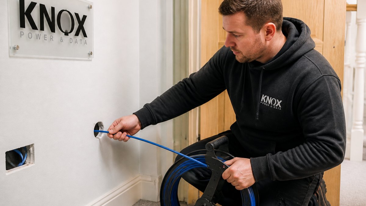
Drilling access holes through wall plates and framing
Drill your first hole at the network equipment location, where cable exits the wall. Mark it carefully with a pencil and level.
Drill straight through the wall plate, a perpendicular hole is cleaner and stronger. Use slow, steady pressure and let the drill do the work.
Drill the exit hole at the wall plate location, again straight through.
Inspect both holes: they should be clean and smooth, since rough edges catch cable. Smooth any rough edges with fine sandpaper.
Using fish tape or cable rods to pull cable without snagging
Feed the fish tape or rod through the cavity from the exit hole. Go slowly, push steadily without forcing, and if you hit resistance, pull back and try a different angle.
Once the tape emerges from the entry hole, attach the Cat6 with a connector or tape. The connection must be tight and smooth, any bumps catch on the wall.
Apply cable lubricant to the jacket before pulling; it significantly reduces friction.
Pull the cable back steadily and evenly, jerking damages cable or dislodges the connection. A typical wall run takes 2-5 minutes.
Protecting cable with sleeves and managing tension
Slide a cable sleeve over the Cat6 as it emerges, protecting it and looking neater. Trim it flush with the wall plate.
Don't pull too tight, excess tension stresses cable and connectors. Leave a 50mm loop at both ends for future adjustments.
Bundle excess cable neatly with cable ties or velcro, avoiding tight zip ties that crush the jacket.
Cat6 Cable Wall Socket Installation and Termination
Once cable is through the wall, terminate it properly, poor termination kills network speed and reliability.
Installing low-voltage brackets and wall plates
Mount the low-voltage bracket inside the cavity first, behind the wall plate, using fixings suited to your wall type (plasterboard anchors for drywall, timber screws for studs).
Slide the wall plate over the bracket, flush with the wall surface, and secure it with the provided screws so it sits level and square.
Crimping and terminating Cat6 at RJ45 connectors
Strip about 50mm of jacket to expose the four twisted pairs, taking care not to damage the individual wires.
Untwist the pairs slightly and arrange them for your wiring standard, most installations use T568B (white-orange, orange, white-green, blue, white-blue, green, white-brown, brown).
Insert the wires into the RJ45 connector so they sit flush at the tip; any gaps mean the connection will fail.
Test immediately with a network cable tester to verify all eight wires are connected.
Understanding Ethernet Cable Distance Limits for Your Network
Cat6 has strict distance limits; exceeding them degrades speed dramatically. Knowing them prevents wasted installation effort.
The maximum recommended Cat6 distance is 100 metres from switch to endpoint. Beyond that, signal degradation becomes problematic.
Most residential runs are 10-30 metres, well under the limit; commercial buildings often need longer runs, where distance limits matter most.
Cat6 also has bend-radius limits: never bend tighter than 51mm (four times the cable diameter), as tighter bends damage the twisted pairs and cause signal loss.
Electrical Code Compliance and Safety When Routing Cable
Routing Cat6 through walls means working near electrical systems, where mistakes create serious safety risks. Compliance protects your installation and your safety.
Separation requirements between Cat6 and electrical wiring
Cat6 must maintain minimum separation from electrical wiring; the Building Regulations (BS 7671) and other standards require this to prevent interference.
The rule: keep at least 50mm from electrical cables, both low-voltage (mains) and high-voltage. If you can't, use a barrier or conduit between them.
In practice, run Cat6 in a different cavity from electrical wiring where possible; if they must share one, separate them with a physical barrier such as plastic conduit or cable tray.
Never run Cat6 in the same conduit as electrical wiring, it creates electromagnetic interference that degrades performance and violates safety standards.
Fire blocking and fire-rated wall penetrations
Fire blocking slows fire spread between floors and compartments. Drilling through it creates a gap fire can use, so you must seal it properly.
After pulling Cat6 through fire blocking, fill the gap with fire-rated sealant. Use an approved intumescent sealant that expands when heated.
Never leave gaps unsealed. Unsealed penetrations violate building regulations and insurance requirements. They also compromise fire safety for the entire building.
Some walls have fire-rated requirements printed on them. These walls need special handling. If unsure, consult the building's original plans or contact a qualified electrician.
Testing and Troubleshooting Your Cat6 Installation
Installation isn't complete until you test the connection. Testing catches problems before they cause network outages.
Continuity testing and wire mapping
Use a network cable tester to verify all eight wires are connected in the correct order. The tester sends signals down each wire and checks for continuity. A good connection shows all eight lights on the tester.
Wire mapping tests verify the wiring sequence at both ends. If the sequence is wrong at either end, the connection fails. Most testers show which wires are reversed or crossed.
Common mistakes include:
- Wires in wrong order (most common)
- Broken or pinched wires
- Incomplete crimps (wires not fully seated in connector)
- Wrong connector type (Cat5e instead of Cat6)
Fix these by re-stripping the cable, re-ordering the wires, and re-crimping the connector. It takes 5-10 minutes to correct most problems.
Checking link speed and identifying common faults
Once the tester passes, check actual link speed. Connect to a network switch and verify the connection shows as "1000 Mbps" (gigabit speed). If it shows "100 Mbps" or lower, something is wrong.
Common causes of slow speeds include:
- Excessive cable length (over 100 metres)
- Damaged cable jacket (water exposure or crushing)
- Poor crimps (incomplete wire contact)
- Electromagnetic interference from nearby electrical cables
- Using Cat5e connectors instead of Cat6
Each of these is fixable. Most require re-doing the termination or repositioning the cable away from interference sources.
Test the connection under load. Transfer a large file and monitor the speed. Consistent gigabit speeds (around 900-950 Mbps) indicate a healthy installation.
When to Call a Professional for Cat6 Installation
Some installations are best left to professionals. Know when to call in help.
Call a professional if your run exceeds 50 metres through multiple walls.
Call a professional if your route must cross fire-rated walls. Fire-rated penetrations require specific knowledge and materials.
Call a professional if you encounter extensive electrical wiring or plumbing in your wall cavity.
Call a professional if you're uncomfortable drilling through walls or working at height. This isn't laziness, it's recognising your limits.
At Knox Power & Data, our NAPIT-registered team handles Cat6 installations of any complexity.
Frequently Asked Questions
How do you route Cat6 cable through an internal wall without damaging it?
Start by planning your cable route and identifying wall obstructions using a stud finder. Drill access holes at the top and bottom of the wall cavity, then use a fish tape or cable rod to guide the Cat6 cable through. Pull slowly and steadily to avoid snagging the cable on nails, splinters, or sharp edges. Use a cable sleeve around the cable for extra protection, and never exceed the recommended bend radius of 25 mm for Cat6. Test the connection after installation to confirm continuity and link speed.
What tools do you need to run Cat6 through walls?
Essential tools include a stud finder, drill with appropriate bits, fish tape or cable rod, wire strippers, crimping tool for RJ45 connectors, cable tester, and a continuity tester. You'll also need a drywall saw or hole saw for access points, a level for accurate placement, and cable sleeves or conduit for protection. Safety equipment like eye protection and work gloves is important when drilling and handling sharp tools. A voltage tester is critical to confirm no electrical wiring is present before drilling.
How far can an Ethernet cable run before signal loss?
Cat6 cable supports reliable transmission up to 55 metres for standard applications, though the official IEEE standard specifies 100 metres as the maximum distance for a single run including patch cables. Beyond 55 metres, you may experience signal degradation and reduced link speed. If your network requires distances exceeding this limit, use a network switch or repeater to extend the run, or consider fibre-optic cable for longer distances. Always test your connection after installation to verify actual performance.
Can Cat6 cable run alongside mains electrical wiring?
No, Cat6 cable must be kept separate from mains electrical wiring to prevent electromagnetic interference. Building Regulations require a minimum separation distance; typically, low-voltage data cables should be at least 50 mm away from electrical cables running in parallel. If they must cross, do so at right angles. Use separate conduits or cable trays where possible, and never bundle Cat6 with electrical wiring. Fire-rated wall penetrations require additional fire-blocking material around the cable opening. Consult BS 7671 or local building control for specific requirements in your area.